REMEMBER:

•  Add your name to your projects
•  Save Photoshop projects as PSD and JPG
•  Save Bryce projects as BR7 and [Save Image As] JPG
•  Save Sculptris projects as SC1 and JPG and export it as an OBJ.
•  Save Rhino projects as 3DM and JPG
•  Save Flash projects as FLA and go to FILE>PUBLISH SETTINGS and publish as SWF and JPG
•  Upload finished projects to your portfolio and/or your DeviantArt page
•  Keep checking your grade on PowerSchool
DOWNLOADS:
Download Bryce 5 Trial Version
Download Sweet Home 3D
Download Rhino 3D 5.0 Trial Version
Download Sculptris
Download Windows Movie Maker 2.6
Download Java JDK
Download Greenfoot

Friday, March 28, 2014

Rhino: Basic Room (Floor & Walls)

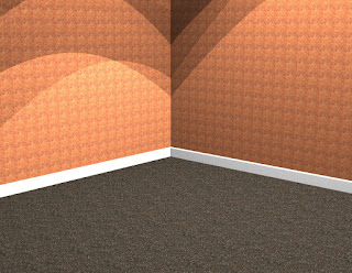
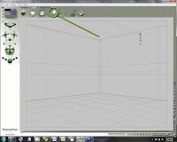
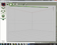
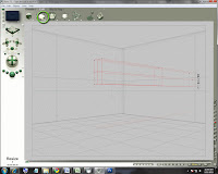
Today we are going to create a basic "room".  Really, it's just a floor and two walls, but we will use it to display some of our Rhino creations.

The room pictured here has a floor (with a texture and a bumpmap), two walls (with texture), and a couple small trim pieces.  I also added some lighting effects.

You may want to create a few different "rooms" (some with wallpaper, some with wood floors, some with wood or painted trim, etc.  Again, these will be your "stage" to showcase some of your creations.

If you are adventurous, you can copy your table (from yesterday) and put it in the corner:
  1. Save your Room
  2. Open up your table file
  3. Select everything (drag a box around it or CTRL+A should do it)
  4. Copy it (CTRL+C)
  5. Open the Room file again
  6. Paste (CTRL+V)
  7. Scale your table (and anything that came with it) to fit nicely in the corner

Wednesday, March 26, 2014

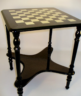
Rhino: Wooden Inlaid Table

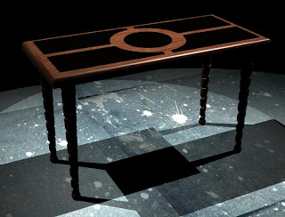
Today we are going to use some of the tools we have become familiar with (boolean difference, pipe, fillet edge, etc.) to create an "inlaid table with carved wooden legs".

The beginning is pretty basic -- create a flattened box that will be our table top.  We will then make some truncated cones for legs.  We will add another box to act as "inlay" in the top of our table, and we'll cut away pieces of that.  After we add some lighting and textures the effect should be complete.

Tuesday, March 25, 2014

Rhino: Table Legs & Top


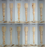
Today we are doing a project very similar to the goblet or vase.  We are going to use the "Revolve" tool to turn some table legs.  Try a few different designs and some different textures.  Remember to add gloss (50 is really shiny) if you want them to appear varnished.

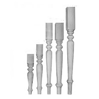
Notice that some are shorter and some are taller, but they have very similar designs.

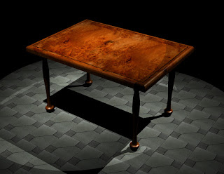
If you look at the table design below, you can see turned wooden legs and it really helps to accent the table.

 
Process:
  1. Begin with "Small Objects - Inches"
  2. Select the front or side viewport and expand it
  3. Draw a profile of a table leg.  Standard table legs are approximately 29" tall
  4. Create your table leg using the Revolve method from the "Goblet" project.
1. Use the Curve tool to draw the profile of a table leg.
2. Select the curve (that you just drew)
3. Type "Revolve" and press Enter
4. Set the Axis in what will be the center of your table leg.
5. Type "0" and press Enter.
6. Type "360" and press Enter.

Rhino: Basic Table with Turned Legs

Today I would like you to make a table using the legs you built.
  • First, make sure the legs are long enough for a proper table.  Dining table legs are typically about 29" (inches) and coffee tables or end tables are much shorter.
  • Put a box on top of four table legs.  The box (table top) can be square or rectangular.  Make it at least a couple inches thick -- but remember that dining tables are typically 29-30" tall.
  • Try a FilletEdge command.
    • Type FilletEdge and press Enter
    • Set the fillet number to 1 at first.  
    • Select all four top edges of the table top.
    • Press Enter
    • If the table "blows up" (goes all crazy) do an Undo (CTRL+Z) and try again with a smaller number.
    • If the table isn't filleted (rounded) enough, do an Undo (CTRL+Z) and try again with a larger number.
  • Add textures, gloss, bumpmaps (if necessary)
  • Add a floor:
    • Scroll/Zoom out in your TOP viewport
    • Select the Box tool and make a box large enough to be a floor (maybe a couple inches thick)
    • Add textures, gloss, bumpmaps (if necessary)
  • Add some items (i.e. goblet, vase, plates, bowls, etc.) to the top of the table.
  • Add some spotlights at different angles to add interest to the scene

Monday, March 24, 2014

Rhino: Funky Coffee Table

Begin by opening the "Room" project you built yesterday.  Save this empty room as "Coffee Table" so you don't accidentally save over your empty room.
 Making the Table:
  1. Use the Curve tool to draw a shape for your "funky coffee table", connecting the last point with where you started drawing.  Strange designs like this were popular in the 50's-70's.
  2. Select the curve you just drew [if not already selected] and type "ExtrudeCrv" -- then press Enter.
  3. Either drag your mouse up/down in the front or side viewport to select the thickness of your table, or enter a number (in inches).  This will create a "band".
  4. Type "cap" and press Enter.  This will make the band appear solid.
  5. Drag your new table top up into your room scene about where you would want your table top to appear.
  6. I suggest doing a "FilletEdge" command next to round the top [and possibly the bottom] of the table edge.  
  7. Add a table leg using the Truncated Cone shape:
    1. Click in the top viewport where you would like to attach the leg.
    2. Drag out to set the width of the top of the leg.
    3. In the front or side viewport drag down to select the length of your table leg.
    4. Back to the top viewport, select the width of the bottom of the table leg.
    5. Drag the leg up (in the front or side viewports) so that it rests on the floor.
    6. Select the new table leg and type "Copy".
    7. When prompted, click in the center of the table leg (in the top viewport).
    8. Move the mouse in the top viewport and click where you want additional legs.  Do either 3 or 4 total legs.
  8. Adjust the table height (drag the table top) so that it rests on top of the table leg.
Finish Up:
  • Put some items on the table -- perhaps a coffee mug, a plate, a vase, etc.
  • Texture your table, legs, objects, etc.
  • Create a spotlight (or 2 or 3) on your table to highlight your new creations.

Note: If you go to the "Projects in Computers" folder on the "L: Drive" you will be able to view the 3D Graphics folder which has TONS of textures, bump maps, models, etc. Check them out.

Friday, March 21, 2014

Rhino: 3D Goblet or Vase

Today we are building a 3D shape such as a goblet or vase by drawing the profile of the shape, then using the "Revolve" command to make it a 360˚ object.
  1. Use the "Curve" tool (either "control point curve" or "sketch") to draw the shape in the "Front" or "Right" viewport -- use the red "base line" as a "floor". 
  2. Press ENTER to get out of the "curve" menu.
  3. Click on your new line (to select it).
  4. Type "Revolve" in the "Command:" line.
  5. Draw the "Axis" (use Shift to keep the line straight) down [what will be] the center of your object and press Enter.
  6. Type "0" for the "Start Angle" and press Enter.
  7. Type "360" at the "Revolution Angle" prompt and press Enter.
  8. Press "Delete" to remove the original curve that you drew.
  9. Shade the Perspective viewport and view your object from different angles.
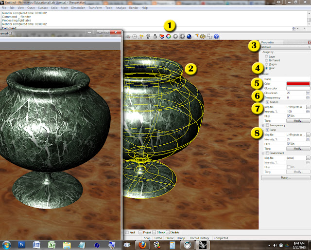
To add texture to your object, you can do the following steps:
  1. Click the Object Properties button (the little rainbow-donut looking thing)
  2. Select the object that you would like to texture
  3. Use the pull-down bar [which probably says "Object"] to select "Material"
  4. Choose "Basic"
  5. To adjust color simply click the Color bar and choose
  6. You can adjust the amount of gloss (the lower the number, the higher the gloss) and the amount of transparency (i.e. to make something look glass-like)
  7.  To add an actual texture (marble, rusty metal, wood, etc.) click the "Texture" button and select a picture from your computer.  There is a folder full of textures on the server (L:\Projects in Computers\- 3D Graphics\Textures - with Bumpmaps) which you can pull from as well.
  8. To add a tactile texture (bumpiness, for example) you can apply a "bumpmap" by clicking on the "Bump" button and adding a picture.  Again, I have a folder full of bumpmaps available for your use (L:\Projects in Computers\- 3D Graphics\Textures - with Bumpmaps\BUMPMAPS).
 Below you can watch a tutorial video showing this project:
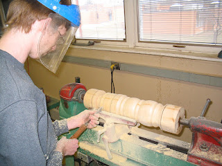
This works much like the way in which a woodturner shapes wood.  They follow a template as the block of wood revolves and they slowly cut away at the wood.
Here are some examples of woodturned goblets: 

Thursday, March 20, 2014

Rhino: Beginning Rhino: Castle

Today we begin using a program called Rhinoceros 4.0 -- a 3d modeling program which is used in a variety of industries around the world.  Rhino is used in automotive design, marine design, jewelry design, shoe design, etc.

You can download a trial version (which is limited to 25 saves) here:
http://www.rhino3d.com/download/rhino/5.0/evaluation 
(This is version 5.0 but it works the same)

Check out a gallery of designs made with Rhino here:
http://www.rhino3d.com/gallery/1

To begin with, we're going to be opening a file and copying (CTRL+C) and pasting (CTRL+V) different pieces to build a small castle.

To begin with:
  • Go to HELP > Learn Rhino > Open Tutorial Models > Level 1
  • Open Start.3dm
The following links open the Rhino Level 1 Training Manual and the Rhino Level 2 Training Manual.  We will be doing some projects out of these books.


LEVEL 1  /  LEVEL 2
You can download the manuals from the Rhino site as well.

Tuesday, March 18, 2014

Bryce: Streaming Light

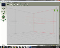
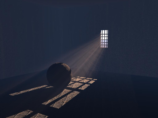
Today we are going to do a project that adds realism to a piece of work, but requires some specific steps and setup.

Step 1: Disable Sunlight

Before beginning, go into the SKY LAB - Click Sky & Fog and then the "Rainbow" then click Disable Sunlight.
Step 2: Create a Block
Use the Resize tool to flatten the block into a wall shape.
Step 3: Reposition the Wall
Use the Reposition tool to move the wall back.
Step 4: Resize the Wall
Use the Resize tool to raise the height and expand the width of your wall.
Step 5: Create a Second Wall
Do a CTRL+C (to Copy) and then CTRL+V (to Paste)
Hold SHIFT and drag ROTATE to make a wall at a 90 degree angle
Step 6: Reposition the Second Wall
Use the Reposition tool to move it to the back.
Step 7: Create the Ceiling
CTRL+C (Copy) and CTRL+V (Paste) to create a new "Wall"
Use the Rotate tool (Z Axis) while holding SHIFT to make the new wall flat.


Step 8: Move the Ceiling Up
Raise the ceiling up using the Reposition tools.
Step 9: Resize the Ceiling
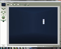
You want to have a ceiling large enough that you don't see light hitting the floor in your room.  Use the Resize tools (Front X and Z Axis) to make the ceiling larger.  Render the scene to make sure you have it covered.  If everything is correct, the rendered scene will be very dark.
Step 10: Create a Window-Shaped Block
Create a block and use the Resize tools to make it "window-shaped".
Use the Resize tool to drag out the Back Z Axis so that it easily goes through the back wall.  This shape will be used to cut a hole in the wall.
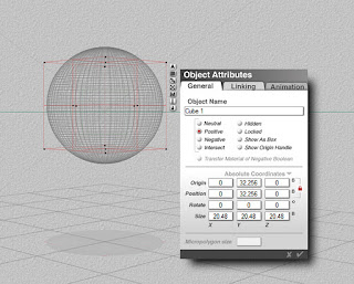
Step 11: Make the Block Negative
With the block selected, click on the A (Attributes) button.
Set the shape as "Negative" and deselect "Transfer Material of Negative Boolean"
Step 12: Make the Wall Positive
Click the A (Attributes)
Select the Positive bullet
Click the check mark.
Step 13: Make the Window Cutout
Select the block (the negative object).
Hold SHIFT and click the wall (the positive object)
Click the G (Group) button.
You should see a cutout shape in your wall.
Step 14: Render Your Scene
If you render your scene now, you should see a window shape.
Step 15: Begin Bars for Windows
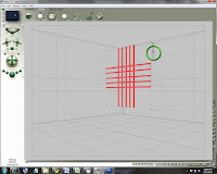
While I personally don't LIKE bars on windows, adding them to this project allows the light streaming through the window to be broken up a little bit more.  It adds some interest to the final render.
Step 16: Finish the Bar
Use the cube in the center of the Resize tool to shrink your cylinder down to the thickness of a bar for the window.
Then stretch the shape out by grabbing the Y axis in the Resize tool to create the final bar shape.
Step 17: Copy the Finished Bar
Do a CTRL+C (Copy) and a CTRL+V (Paste) to make a copy of the bar.  Then use the arrows on the Reposition tool to drag the bar over.  Continue doing this until you have a series of bars.
Step 18: Group, Copy, & Rotate Bars
Next, hold SHIFT and select all of the bars.
Click G (Group) then CTRL+C (Copy) then CTRL+V (Paste).
Use the Rotate band while holding SHIFT to cross the bars.
Step 19: Reposition the Bars Into the Windows
Use the Reposition tool to move the bars back and into the window opening.
Do a Render to check positioning.
Step 20: Add a Spotlight
Create a new "Square Spotlight" (pyramid shaped).
Use the Resize tool (Y axis) and shorten the light about half way.
Step 21: Reposition the Spotlight
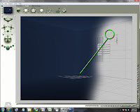
Use the Rotate tool and the Reposition tool to move the spotlight to the outside of the wall facing in through the window.  Note the shadow cast on the floor in the example.

Step 22: Adjust Spotlight Properties
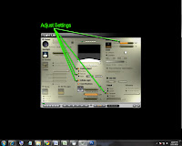
(see image)


Finally, you can add some textures, additional items or even change the color of the light to get a fairly realistic scene.

Friday, March 14, 2014

Bryce: 3D Model Using Symmetrical Lattice

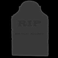
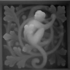
We have used the Symmetrical Lattice tool to build a 3D logo, but we haven't yet tried to build an object to be used in a full scene.  For example, if I wanted to create a graveyard for a Halloween scene, I could make gravestone blocks or even crosses, but what if I wanted more detail?  I could create a "bump map" (a square image where black is the lowest elevation and white is the highest) just as we did with our City Scene.

Here are some examples:


If you're looking for even more detail, you can create a painting in Photoshop such as this:


We are going to use these techniques to build a sword from separate pieces.  For example:
I will use this as the guard at the top of my sword handle.  Notice the gradient so the white part will be thicker and the darker gray will be thinner.  It helps add to the 3D effect.  I could also add decoration (i.e. text) if I wanted to.
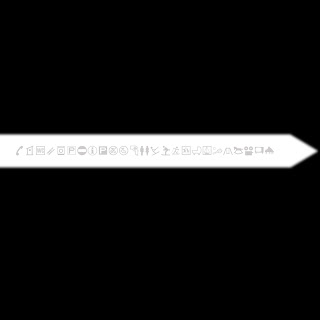
The blade is pretty much just drawn and then a Guassian Blur is applied to soften the edges.  While common sense says a "sharper" edge would make a sharper blade, the blur gives the edge a gradiant effect, thereby making the edge thinner (or sharper).  Notice the random gray symbols which I can use as engraved characters.

We would still have to create a handle, align things properly, and group them, but you can see that the majority of the work is done now.

Wednesday, March 12, 2014

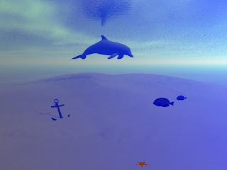
Bryce: Underwater Scene

First of all, create your overall scene (don't worry about making it underwater yet):

  • Change your plane into something natural which you would find under water (i.e. sand)
  • Add a Terrain and erode it to look natural and weathered, then apply the proper texture
  • Add some items that you would find under water (i.e. anchor, fish, dolphin, etc.)
  • Import and texture your Sculptris Underwater Creature that you built last week.
  • Add a water plane and move it up above your scene to create a water surface.
  • Try different skies until you find one that looks more realistic.
  • Next, add some haze and fog and adjust the colors accordingly.
  • Finally, add a spotlight and a filter to make light ripples.
Below is a gel image:

Monday, March 10, 2014

Bryce: Outer Space

Todays project is really the absence of terrain... and sky... and haze.  It's space.  In this instance we will be creating a moon, stars, a comet or two, and [if you want] some sort of space craft.

I am also including a video tutorial below if you need the extra help.
Here's another tutorial on producing photo-realistic planets:

Friday, March 7, 2014

Assignment: Continue Imported Object Scene

I want you to finish creating a scene using imported objects.  Make it a fully involved scene using elements of Bryce, creative uses for things like Terrains or Symmetrical Lattices, and then an imported object that you get angled, textures, etc. to look like it fits into the scene.

Upload your finished version to your blog.

Thursday, March 6, 2014

Bryce: Importing External Objects

As we learn object modeling in Rhino [which we will begin after Winter Break] we will be saving models to be used in other programs (like Bryce).  Fortunately there are also web sites which sell and/or give away external models which you can use to build your 3D projects.  For example, let's say you are trying to create a medieval scene with a knight on a horse, but you don't know how to "build" a horse.  You can download a pre-built horse and place it in your scene.

So where can you get 3D models?  Well, there are many in your L: Drive already.  You can browse through those models [most don't have good descriptions] and experiment a bit.

There are also many websites where you can download models:

Wednesday, March 5, 2014

Bryce: Boolean Difference

Today we will be learning how to create a "Boolean Difference" in Bryce -- basically meaning you cut one shape out of another shape.  The image below features a "cave" that was created by cutting a "symmetrical lattice" (looks like a mountain on top of an upside down mountain) out of a regular "terrain" (a mountain).  You can cut a block out of a sphere... a cone out of a pyramid, or whatever other shapes you might need. 

To begin this process:
  • Place the two shapes together intersecting one another (touching)
  • Select the shape you want to use as a "cutting tool" and click the "A" (Attributes) tool.
  • Select the "Negative" bullet and un-check the "Transfer Materials of Negative Boolean" option.
  • Click the "check mark" to okay the change.
  • Select the shape you want to cut IN to (the shape you want to keep).
  • Click the "A" (Attributes) button.
  • Select the "Positive" bullet mark and click the check mark to okay the change.


Next you have to "Group" the objects to be joined/cut:
  • Select the 1st object (i.e. the "negative" piece)
  • Hold SHIFT and select the 2nd object (i.e. the "positive" piece)
  • If it looks like you have other objects selected, deselect and try again.  You may have to rotate the scene a bit to make clicking easier.
  • With both pieces selected, click the "G" (Group) tool. 


Now you should be able to "Render" your scence and view the cut out shape.